After clones and variations of the venerable WS2812, there finally seems to be a new RGB-LED with integrated controller that actually improves on several characteristics: The APA102, also known as “Superled”. There are two versions on the market, the APA102 and the APA102C, as shown below.

The APA102C comes in a package very similar to the WS2812, while the APA102 comes in a package with an increased metallization area to improve heat conduction. The APA102 is more expensive, possibly owed to the more complicated package. So far, I was only able to investigate the low-cost version, the APA102C.
The controller IC was designed by a Taiwanese company, APA Electronic co. LTD.. Unfortunately they do not have a lof of detailed information on their website. But they were nice enough to send me the original datasheet upon request. I mirrored the datasheets here: APA-102 and APA-102C.
I contrast to the very timing-sensitive one-wire protocol of the WS2812, the APA102 uses a standard two wire SPI protocol – one clock line and one data line. Each LED has two inputs and two outputs which can be daisy chained. At the first sight this may seem wasteful, but it has the advantage of being supported by standard microcontroller periphery and it is insensitive to timing variations. Due to the critical timing requirement it is not possible to control the WS2812 from SOCs with multitasking operating systems, such as the Raspberry Pi. This should not be an issue with the APA102. Furthermore, the data can be transferred at an almost arbitrary clock rate. I was able to control the LEDs with 4 MHz SPI clock without any hitch. It appears that the maximum speed is mainly limited by the parasitics of the wiring. The data format is shown below.

Each update consists of a start frame of 32 zeroes, 32 bits for every LED and an end frame of 32 ones. I am not sure what the “End Frame” is good for, since its encoding is indistinguishable from a LED set to maximum brightness and will simply be forwarded to the next LED. In my experiments, omitting the end frame did not have any impact.
One interesting addition is the “global” field for each LED, which allows to control the brightness of the LED in 32 steps from 0 to 31. When trying different parameters, I was quite surprised to observe that the LEDs did not show any visible pulse-width-modulation (PWM) flicker at all when the global brightness was set to 31. This is quite different from the WS2812, which shows visible PWM flicker when moving the LEDs.
Interestingly, the APA102 started to flicker once I set the global brightness to 30 or below. To understand what was going on, I hooked up my scope to the power rails. When the LEDs are turning on, they draw significantly higher current which leads to a drop in voltage across the power rails. I previously used a similar method to investigate the inner workings of candle flicker LEDs. 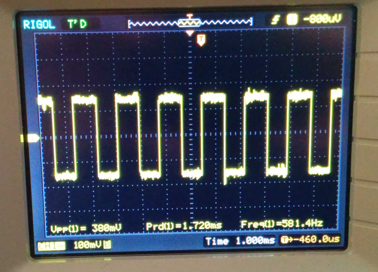
The picture above shows the current modulation for RGB=255,255,255 and the global brightness set to 16 (50%). The pulse width modulation is clearly visible in the voltage signal at a frequency of 580 Hz, very similar to the 430 Hz of the WS2812.
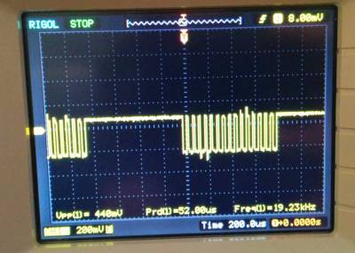
Next, I set the RGB value to 128,128,128 and kept the global brightness at 50%. The result is shown above. Two PWM modulation schemes are superimposed in this configuration. The global brightness is still modulated at ~582 Hz, while RGB value is modulated at an approximately 32 times higher frequency, 19.2 kHz. This frequency is significantly above the flicker fusion threshold, even when moving the LED around, leading to an apparent constant brightness.
The very high PWM frequency is a pretty nice feature of these LEDs. In combination with the higher update speed due to the SPI interface, they should be much better suited for persistance-of-vision applications than the WS2812.
In summary, the APA102 show significant promise compared to the de-facto standard WS2812:
- They can be controlled with a standard SPI interface. No critical timing required and much faster than the one wire protocol.
- They have an extremely high PWM frequency, allowing flicker-free POV applications.
- They are available in a special package with better heat sinking.
What could be improved:
- I don’t find the global brightness setting terribly useful, considering that using it leads to visible flicker and it basically adds dead weight to the data transfer.
- They are more expensive than the WS2812.
Edit: I published more information about the inner workings of the APA102. Furthermore, a first release the of light weight APA102 lib is available.

Should you wonder, why on earth I am posting blurry screenshots of a digital scope: I did not have an USB stick around… 🙂
Usually you have an end frame because the device you’re communicating with needs the clocks to completely move the data from its internal shift buffer; in the case of this device, it’s clearly 32 bits wide.
Good point, that could be the reason.
Are these avaible at mouser or farnell/element14?
I got them off aliexpress.
As of 20140923 a search at Mouser for “APA-102” returns no results. Interestingly, a search for “WS2812” returns only one (non-stocked) product and a search for “WS2812B” returns no results. Oh, well.
You will find very few products of smaller chinese/taiwanese companies at Mouser, Farnell, Digikey or similar distributors. Your best bet is to order them on aliexpress or ebay.
Adafruit has them in packs of 10 (item #2343; they also sell them soldered onto a variety of form factors under the rebranded name “DotStar”) for about twice what you would pay on Ebay or AliExpress, but you won’t have to wait on the slow boat from China 😉 I order from Adafruit when I’m prototyping something, but for production you’ll probably want to go with Alibaba or Ebay.
How do these compare to lpd8806 in terms of speed?
Very useful post Tim. Did you actually use the APA102s with a Raspberry Pi? I’m wondering if it’s possible to run them directly from the Pi’s 3.3V GPIO (using a 3.3V power source for the LEDs as well), or if I need some kind of level shifter in between.
Thanks!
Good point! But no, i have not tried it.
Hi Alex,
leaving comment for future reference if someone googles this article. I am currently running APA102 led’s with Raspberry Pi 2 without any level shifter, only the power source is rated 5V. I have almost two meters APA102, 117 leds hooked.
So to sum up, at least on my Pi it works with RPi’s 3.3V GPIO. I use them with hyperion software.
I have it same as you. But big problems. 513 APA102C are connected. The LED’s are flickering when they should be off. During power on they flicker as well. Sometimes more somtimes less. The pi is powered on with the strip by a 5v 30A power supply. The stripe get every 2m a power line wich is a circle with 4mm cables. I don’t can fix the flickering. Please help 🙂
@Dirk did you connect the strip ground to supply ground AND the PI Ground? If not try that. seems arbitrary but i’ve read that it is needed.
For those wondering about the end pattern.
The answer becomes easier to understand once you know the datasheet is wrong.
First of all I was wondering when the LEDs take over the data without chip select, which I explain first.
You start with a zero pattern followed by at least 3 ones for the first LED data.
The first LED takes over the first data because it is followed by the 32 zeros.
The second LED gets a completely different data pattern from the first one.
The first LED removes his data from the stream replaced by zeros, so the second LED sees 64 zeros directly followed by the second LED data and then again filter it’s own data with the 3rd LED seeing 96 zeros first.
Now about the one pattern at the end.
From the pattern it is full powered on, but it is for LED n+1, so it addresses the first LED after your chain, which don’t exists – no worries about that as it is not special end marker.
In fact the data doesn’t even matter, but sending ones won’t be interpreted as a start pattern.
But the one pattern is required for the LEDs to shift the filtered data stream to the next LED.
Each LED needs an additional half clock cycle for filtering the data.
2 and 3 LEDs need an additonal ones, 100 and 101 LEDs need 50 additional ones clocked.
More ones clocked won’t matter, but the 32 bit in the datasheet only works for up to 65 LEDs.
In a workload with regular updates you might not notice, because the next update will clock out the previous data to the remaining LED.
Another thing to notice is that there are different LEDs on the market.
I got APA102C with swapped green and blue.
Be carefull when you mix LEDs from different suppliers.
Thanks for the explanation Bernd, I’ve been playing with those leds since yesterday, I really love them compared to the ws2812, I run them on a 35MHz SPI bus without issues on the raspberry pi (I’m shifting up mosi & clock signals levels, didn’t try without as this has been asked before), impressing refresh rate with my 144 leds strip !
Have you measured the actual refresh rate of the LEDs? I want to build rotational display and I need actual refresh reate about 4kHz…
580 Hz seems like a pretty high PWM rate to see visible flicker, is the flicker only visible when moving the LEDs, like in a POV application? Can you see flicker when the LED is stationary?
I personally find it very distracting. It’s visible when you move your head and the flicker also become more apparent in peripheral vision, which is especially annoying.
In terms of automated SMT-production this component is a nightmare. Reflow temp and time is way below the specs of other ROHS-compliant components and datasheet is not uniform in recommendations (235 +/- 5 vs 230 straight for 10 secs).
Anyone else who faces this challenge? Would love to hear some tips and tricks
Very few of my designs have a 5V rail anymore. Has anyone tried powering these LEDs from 3.3V? (The WS2812B’s I’ve tried work fine at 3.3V, just that the blue LED intensity is down ever so slightly.)
I have to supply 5v every couple of metres to avoid noticeable yellowing, so I don’t think 3v3 would work well.
It’s a good idea to supply power every 50 or so LEDs due to the high current they can potentially draw. I have an application that runs on 3x AA’s (so nominally 4.5V), but it works fine as the batteries discharge significantly. As the voltage drops near the end of the battery’s charge (so, ~3.3V), blue (and eventually green) gets very dim. 3.7V (nominal for a li-poly) would probably work, but 3.3V will probably be a little low to get the full intensity of the blue LED. Taking an educated guess, it probably has a typical 3.2V rated blue LED element and a ~25mA current driver (figure about 1/2 V overhead for optimal operation), so that leads me to think 3.7V is a good minimum to work with.
I bought a couple of POV bike lights in the supermarket. Thet have 7 LEDs, which I am guessing are APA102c because they look just like your pics and completely different from the WS2812. When attached to the wheel of your bike they display “GO!” I can email some pics if you contact me.
Cheers
Do you happen to know the standby current? The WS821x LEDs draw nearly 1mA each, when idle. I was rather hoping for an LED which could draw well under 1 uA when it is off, as currently I have to waste a scarce I/O pin and a MOSFET (to control the LED’s VCC) to use a WS8212B with a battery-powered device.
That is actually a very good point. Unfortunately I don’t know the standby current. My guess is that it is not too low, as the IC is most likely not optimized for low standby current.
I am trying to use APA102’s in place of WS2801’s. My project is to use MIDI note signals from an 88 note piano keyboard to light the respective Led’s. The code I am using was originally written for HL1606’s, but it does work OK with WS2801’s. The APA102’s, however will latch on some Led’s if I go beyond the limit of 64. I have tried all sorts of values for N1, including eliminating it. Finally I gave up and just use two Arduinos with 44 notes each.
The reason for wanting to use APA102’s is that they are available in a 72 led per meter strip. That makes a distance between Led’s that is pretty much identical to the spacing of standard piano keys, which is generally 88 notes in 48 inches.
Thanks to all for the great information in this blog.
See Link at the end.
The global register is useful because it dramatically expands the color resolution available. If you only have 1/256 PWM available the dimmest color available is still quite bright, and the difference between 1/256 and 2/256 is also quite a lot. See the gamma table at:
https://learn.adafruit.com/led-tricks-gamma-correction/the-quick-fix
By combining the global PWM you can get 1/256 * 1/32 = 1/8192 brightness, which allows a much darker LED and much more granularity at the dark end of the RGB scale.
It’s annoying that it’s done this way, but it lets them have 3x 8-bit and 1x 5-bit counters, rather than 3x 13-bit counters, and also fit into a 32-bit word.
Well unfortunately, it does not quite work that way. The effective brightness is the product of the PWM and global setting. This does not give you 13 effective bits of resolution. For example, how would you encode 3/8192?
I agree with @bd, I believe you can combine the PWM and GBC registers to get 13-bit resolution. I’ve been working on this and have an early port of my SmartMatrix Library to run on the Photon and drive APA102s (original for the Teensy and multiplexed “dumb” matrix panels). Here’s demo code and a video:
http://community.particle.io/t/smartmatrix-apa102-library-open-hardware-photon-apa102-shield/21562
> how would you encode 3/8192?
RGB: {0x03, 0x03, 0x03} GBC: 0x01
Here’s a more generic demo and simpler code that’s easier to understand:
https://github.com/FastLED/FastLED/issues/91#issuecomment-169458519
I simplified/improved the code a bit though it’s not optimized for speed, the relevant code in SmartMatrix is here:
https://github.com/pixelmatix/SmartMatrix-Photon-APA102/blob/66209792c6f16351df39ba46fd4f5a8c4fd80515/firmware/SmartMatrix_Impl.h#L183
Tim, I’m interested in your thoughts if you give this a try. I know ~500Hz dithering isn’t suitable for a POV application, but it looks fine to me for fixed position LEDs. Projects like Fadecandy and FastLED’s temporal dithering make use of ~500Hz dithering with good results – I haven’t heard people complain about their flickering except for POV applications or at very low brightness.
Regarding the temporal dithering it depends on the implementation I guess.
I am a bit skeptical about the WS2812, since it is close to impossible to sync to the PWM cycle of the LED string. So there will always be lots of aliasing. Maybe having some modulation is bettern than having none, but it is far from an optimal solution.
Btw, the SK6812 have a higher PWM frequency than the WS2812. So they could possibly be easier.
For the APA102 with a much higher PWM frequency it could in principle be possible to update at 500Hz or 1000 Hz and do super-cycles without too much aliasing. (Still 10x oversampling). In that case it could even be possible reduce flicker compared the the global brightness control.
Interesting idea… 🙂
> how would you encode 3/8192?
I have a feeling you’re asking “how would you encode 3/8192 if the LED was displaying a color at full brightness at the same time?” Of course, you couldn’t do that.
I did some quick tests and found that I couldn’t see a difference between colors like {0x80, 0x01, 0x01} and {0x80, 0x00, 0x00}, so shifting a 13-bit per color PWM value to use the highest non-zero 8 bits and throwing out the rest of the bits shouldn’t make a significant difference.
You could display 3/8192 alongside 255/8192, but not any brighter than 255 without dropping bits.
{0xFF, 0, 0x03} GBC 0x01
{0x100, 0, 0x03} -> {0x80, 0, 0x01} GBC 0x02
{0x200, 0, 0x03} -> {0x80, 0, 0} GBC 0x04
You are right, it is probably not that much of an issue as I initiallity thought.
There is no full 13 bit brightness range available, since the brightness is the product of the 8 bit local and 5 bit global brightness, but this is probqably negligible. (all numbers larger than 255 that can not be factorized into two products are not encodable)
So, it should be possible to come up with an algorithm that finds the optimum encoding of RGB and global brightness for a given 39 bit (3*13) color input. I guess you proposal of normalizing for the brightest value is the easiest approach, which should give good results.
What is the difference between the 102 and the 102C?
RGB color and single color 😉
Hi!
What’s the width of the APA102C led strip?
Thanks.
Tim
Thanks for this. I’ve just written a driver for these LEDs, and on the first pass I ended the bit string with 0xffffffff as stated in the data sheet. I had a long LED strip and was trying to address just the first 12 LEDS. The result was, LED 13 was on bright white.
You mention that the data didn’t matter on that last frame, as long as it wasn’t 0x00000000. So I changed it to 0xff000000. Bingo. No more “last LED on” problem.
Tim, have you tried any SK9822 LEDs yet? LED strip suppliers are suggesting customers use the SK9822 as a substitution for the APA102 due to supply issues. I have some on hand and was trying to reproduce your experiment with the scope to see the GBC PWM frequency, and I can’t get anything that looks like PWM to show up on the scope, though I can with an APA102 LED. I’m guessing the GBC PWM frequency is very high on these LEDs. I have some extra, let me know if you want any and I’ll send them your way (hopefully you have my email through this comment).
Some people told me that they had issues with the SK9822. I have not been able to take a look by myself, but there are some devices coming my way.
Regarding seeing the PWM frequency: Maybe you need to add a current sensing resistor to the power line to see somethine.
Wonder if these would be suitable for LED retrofitting a broken TV? The backlight has gone o/c but most of the LEDs test fine and my repair lasted about a month so evidently the problem wasn’t the strips I moved around.
My thoughts are to replace just the top and bottom two rows of LEDs but retain the original optics so that I can select different screen modes for film use, as well as a “ticker tape” with say just red turned on for ultra high OLED-like contrast without needlessly wasting power in the backlight.
The main reason why LED TVs fail is that the backlights always overheat, some manufacturers have started to add internal bypass/OVP diodes so one failed LED (short or open) just results in a dim area and not total failure.
I found that nearly all of these can indeed be connected in series but the data lines must be current limited and damped correctly, found that 1K is about right to limit current and if you want to be really sure use a proper resistive divider.
Also this somewhat mitigates diode failure (cough knockoffs /cough) as the resistors will somewhat compensate for a fried IC.
In addition add 5V6 zener across each diode just to make sure, for the sake of the extra $0.04.
Thermal pads on the back wouldn’t go amiss here and might have prevented some of the diode failures documented earlier, a good source is the backing sheet from dead plasma panels.
Tim,
Thanks for the in-depth information. Since this website is already very well linked to the Google term “APA102” I would like to mention that your mirrored datasheets at least for the APA102 (without C) contains some wrong information. The package for the “genuine” version APA102 is wrong, the marker is on the opposite side.
Please check this link from Neonworld, Taiwan.
Click to access 1523873502.pdf
The datasheet also contains some useful information about the chip itself. It specifies 15MHz a the maximum clock and limits the VCC to 9V (other text says 7.5V). Maybe this is interesting for people who want to “overdrive” the LED for short terms?
BTW: I choosed the geuine APA102 with the larger housing sourced from Neonworld (which seems to be APA electronics directly). All chinese copies use the PLCC “C” housing, so I hope this decision will prevent me from copies with mixed colours, wrong pin 1 markers etc. etc. The quality of the delivery was very good, sealed bags with defined MSL level and moisture card. No failures so far.
I just see that the IC provides true current sinks for the LEDs, so there is no sense in driving higher voltages. But it may answers a question from Jamieson (see comments above) asking if 3.3V would be OK. The answer from the datasheet is clearly no at this point.
Has anyone experience with TTL level for SPI signal instead of CMOS?
Background: I would like to power the APA102 with 5V but drive the SPI signal (ClK and Data) with 3.3V MCU without level shifter
I have a few questions. What is the PWM depth used by the LEDs? How does it respond if you lower the voltage to 4V and 3.3V? The total current consumption is 30mA? What is the current consumption for each color? How noticeable is the flicker?
Does anyone have experience with addressing a large number of apa102 in a string?
I am planning an art project that would require 10k LEDs.
no personal experience, but do a Google search for “apa102 clock drift” and you’ll find an issue you may run into