A couple of weeks ago I reported about a new type of RGB-LED with integrated controller, the APA102. One of the interesting new features of this device is a two-wire SPI interface instead of the proprietary one-wire protocol of the more common WS2812. Many microcontrollers have hardware SPI functions, which allow easy control of these LEDs, as opposed to timing critical bit banging. But it turned out this was not the end of the story. As pointed out by Bernd in a comment, there is some discrepancy between the datasheet and the actual behavior of the devices when it comes to the “end frame”. Reason enough to subject the APA102 to more scrutiny.
The diagram below summarizes the APA102 protocol as found in the data sheet.

To investigate the functionality of the AP102, I connected an ATtiny85 to the clock and data input lines and used a logic analyzer to probe both the input and output lines. The microcontroller was programmed to output various bit patterns as described below.
I focused my investigation on four areas:
- Behavior of the “Start Frame”
- Function of the “111” bits in the “LED Frame”
- How data is forwarded to the next device
- Impact of the “End Frame”
The Start Frame
I varied the number of zero bits in the start frame from below to above 32. It turns out that a minimum of 32 zeroes are required to initiate an update. Increasing the number of zeroes does not have any impact. The LED frame is identified by the first one bit following the start frame.
The LED output color is updated immediately after the first valid LED frame. This is quite interesting, since it means that almost arbitrary update rates of the APA102 are possible. However, this may lead to a “staggered” update for longer strings, where the first LEDs in a string are updated earlier than the later ones. The best way to work around this is to use a sufficiently high SPI clock rate.
The LED Frame
As noted above, the most significant bit of the LED frame has to be “1”, since it is used to identify the start of the frame. It appears that the next two bits serve no function and can have arbitrary values. To stay compliant with the data sheet, it makes sense to set them to “1”, though.
Data forwarding
The APA102 receives a valid SPI signal and outputs a valid SPI signal to the next devices. By definition, the data line is valid only during the rise edge of the clock signal. This resulted in an interesting problem for the APA102 designers. Simply feeding the input signal to the output would not leave enough time to evaluate and possibly alter the incoming data and could create all kinds of race conditions.
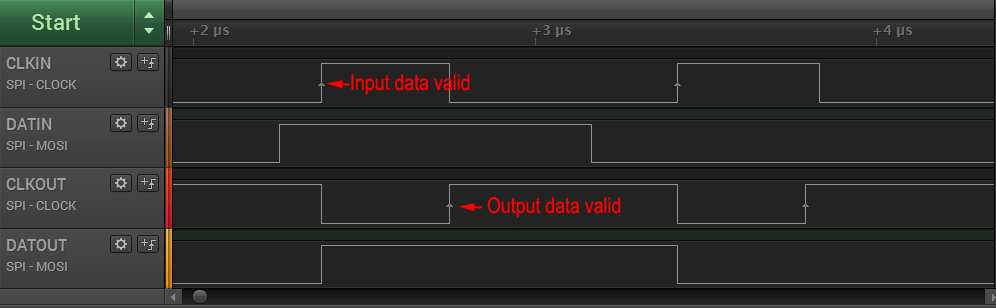
To work around this issue, the APA102 delays the data on the output by half a cycle. As shown in the figure above, this is accomplished by inverting the incoming clock signal at the output. The data output is forwarded during the rising edge of the incoming clock, but only becomes valid for the next device at the rising edge of the outgoing clock.
This design is quite ingenuous as it does not require any internal clock source. It does, however, have implications for the protocol: Since the data for each subsequent LED is delayed by half a clock cycle, but the clock is not, additional clock cycles have to be fed to the string even after all data has been sent. This is the sole reason for the existence of the “End frame”, as discussed below.

The diagram above shows how entire LED frames are forwarded from one device to the next one. Once a device detects a start frame (more than 31 zero bits), it will interpret the next “1” bit as start of its own LED frame. 32 bits are clocked into the PWM registers, while zeroes are pushed to the output. After the entire LED frame as been read, any subsequent data is simply forwarded until another start frame is detected.
The End Frame
As we have learned above, the only function of the “End frame” is to supply more clock pulses to the string until the data has permeated to the last LED. The number of clock pulses required is exactly half the total number of LEDs in the string. The recommended end frame length of 32 is only sufficient for strings up to 64 LEDs. This was first pointed out by Bernd in a comment. It should not matter, whether the end frame consists of ones or zeroes. Just don’t mix them.
Furthermore, omitting the end frame will not mean that data from the update is discarded. Instead it will be loaded in to the PWM registers at the start of the next update.
Summary
In summary, each update of an APA102 based LED string should consist of the following:
- A start frame of 32 zero bits (<0x00> <0x00> <0x00> <0x00>)
- A 32 bit LED frame for each LED in the string (<0xE0+brightness> <blue> <green> <red>)
- An end frame consisting of at least (n/2) bits of 1, where n is the number of LEDs in the string.
Unlike the WS2812 protocol, no waiting period is required before the next update. As discussed before, I strongly suggest to only use the full brightness setting (31) to reduce flicker.
I have no recommendation for a maximum or minimum SPI clock speed. There is no specification for this in the datasheet. So far, it seems that the LED is able to handle any clock setting that is thrown at it. I had no issues with 4 MHz and others have successfully tested 10 MHz and above.
Light weight APA102 library
I uploaded an initial release of the líght_apa102 library based on above findings, a companion to the light_ws2812 lib. You can find the code on github.

Just thought I’d let you know, I’ve had APA102 strip respond just fine to a BeagleBone pushing 60MHz SPI data.
Nice! So the limit seems to be rather in the driver and connection.
Does the BB support 5V I/O or did this work properly with 3.3V
BeagleBone is 3.3V only. The APA102 strip didn’t seem to have a problem reading the lower logic level.
Thank you for sharing your work.
I have chosen APA102 LED for my experiments with music lights and I am a bit confused about all available strip and library options.
My planned system is Raspberry Pi B+, APA102 strip with 60 LEDs and, to be safe, some level shifter.
Could you please clear some questions?
1) So, I’ll need to enable SPI in kernel (Raspbian has a good utility for this) and connect APA102 to RPi’s SPI pins MOSI and CLK (physical pins 19 and 23, according to this http://maxembedded.com/wp-content/uploads/2014/07/Raspberry-Pi-GPIO-Layout-Model-B-Plus.png ) through a level shifter. Level shifter will have common ground with both RPi and LED strip’s power source, and will receive +3.3V from RPi and +5V from the LED strip power supply, right?
2) Are all APA102 strips logically and electrically more-less equal? Can I freely replace this one:
https://www.adafruit.com/products/2240
with this:
http://www.amazon.de/APA102-Leds-Meter-Streifen-Weiss/dp/B00LV8M13O
or this:
http://www.ebay.com/itm/APA102-30-48-60-72-144-LED-Dream-Color-Strip-Light-Individually-Addressable-DC5V-/281555260661?pt=US_Night_Lights&var=&hash=item418e0054f5
?
3) How your library differs from these:
https://github.com/adafruit/Adafruit_DotStar_Pi
https://github.com/tvdzwan/hyperion/wiki/Hardware
?
Have you discovered some important bits about APA102 which are integrated in your library and might be missing from other libraries?
I myself am looking for some way to control LED strip through node.js. I’m better with C++ and Javascript and not Python.
Thanks again,
Martin
Hi Martin,
the strips look good, in general. Unfortunately I am not really familiar with Raspi solutions to drive these strips, so I can not help you in that regard. Sorry..
I have not done a comprehensive comparison between libraries. I believe that the adafruit library was published after mine, so this is a moot point. I am also not really fond of their rebranding and publishing things without proper reference…
Hyperion is an awesome project. I have never tried it, but since it works with other SPI based RGB-LEDs, I suppose it will also work with the APA102.
This is a nice read on APA102, Tim! So good to read your work and your findings.
thanks for your research.. got my code working much faster than without it… I am having some issues with the global field though… I would like to try out the dimming feature but the results are not at all as expected… have you played with that field at all?
I have not used the global dimming feature too much, due to above mentioned flickering issue, however when I tried it, it seemed to work normally.
What are your observations?
Mostly that the amount actually dimmed didn’t seem to correlate to the 0-31 value in the global. 16 worked, most of the lower values were either off or randomly dim. This may still be a code error on my part (very rare :)) so still looking at that. If it worked for you, may well be a bug on my part.
Also, not sure where you are, but I plan to install these lights (like 1100 of them) in a cofferred ceiling. have you had any experience with potential building code issues? how best to distribute power? I live in California so those concerns scare me a little.
Thanks again for your help.
Does anyone have experience powering these LEDs from a 3.3V supply?
The data sheet shows an internal 4.5V regulator, so driving VDD at 3.3V would be way out of spec. One thing to watch out for when you don’t drive the voltage high enough is a design that works OK on certain batches of parts but looks horrible when you mix devices from different production lots. This can cause sadness when you go from your small-scale prototype to your full design.
Hi !
would you recommand APA102 over WS2812 ?
I want to create a project but if i go with a long LED strip I am afraid of the 800KHz limitation on WS2812 which can lead me to a low fps…
Thanks !
Malus
They are definitely better, but also more expensive.
Thanks for taking the time to write this up. The manufacturer’s data sheets are really bad. This cleared my questions right up. Thanks!
Hey guys, I need a little help on how to run a very long string of these together .. like around 1200. I am not familiar enough with electrical stuff to figure out the best way to power them. I know I will have to inject a power supply every few meters, and I want to provide enough power that I can go full white. Here are the thoughts through my head so far… looking for someone to help out!
1. do I distribute 110AC around the run and provide 5V supplies? Or do I distribute say 24VDC and run 5V buck converters ( found some for auto use with fairly high current). leaning towards 110AC.
2. When I insert a power supply, I was thinking of breaking Vin, but letting ground run continuous…. If I have all my 110AC outlets on the same run from my breaker, should I also cut the ground run? seems like if I don’t, there would be massive current on that wire, but SPI needs ground too. Or do I just tap ground at each power supply?
3. I found a pretty cool part (to me) called a SPIsolator: http://www.analog.com/en/products/interface-isolation/isolation/spisolator.html
would be a lot more work, but from my limited understanding, I could insert this across all four wires of 2 strips of LEDS, add a new power and ground in to one side, and everything is isolated… but is this needed?
sorry for the wordiness, and appreciate any help.. thanks!
Kevin,
What type of power supplies you use is up to you. Distributing 24Vdc if you don’t already have it has the disadvantage that you have two regulators in series: one from 110V to 24V, and one from 24V to 5V. This means that you will have two times a conversion loss.
You don’t need to cut the ground wire of the strip.
All current that you deliver to one strip to the local 5V will return through the corresponding ground. Therefore, the connecting ground will only carry the (very small) return current of the data signal. Just make sure that you connect each ground directly next to the 5Vdc on the strip.
This means that you won’t need the SPIisolators either.
Thanks for the reply… So 110VAC sounds like the way to go. So it sounds like you are recommending that only the 5V be cut for each strip in series? And the ground will be uncut and tapped into the supply ground at each power supply?
Lets say I want to turn on full white for an extended period… How much current can a strip take over time before it starts heating up? lets say 3M so 180 leds…. that’s 10.8A. Those traces look pretty small on the strip… but again, I don’t know much about this subject… that’s why I am so nervous!
thanks again for the response.
Many thanks, Tim – this post was very helpful!
I may have found another variant on the APA102 – I got a 144 LED/meter strip from ebay, and the LEDs responded correctly to the above protocol, but appeared to be latching the colour – i.e. if I sent (255,0,0) then (0,255,0) and nothing more, only the first red would appear. I stepped through colour changes with a debugger and definitely saw that the colour change expected only occurred when the next frame of data was sent.
I got hold of some Adafruit DotStar LEDs for comparison, and these definitely make the colour change immediately. I even wired up three of each type into one chain to really confirm it!
Other than that, these ebay sourced LEDs look and behave exactly the same. All my online research hasn’t turned up anything similar; the other 2-wire LED protocols
Interesting. I have seen that the company behind the “SK” chips cloned the APA102. Maybe it is theirs? What was the product name? Do you have any close up photos?
This is the item on ebay: http://www.ebay.co.uk/itm/311634528624
That has a close-up, but is pretty generic looking. I’ll try to take one myself and post it somewhere suitable.
Hm… I don’t see anything unusual.
There is a hires photo on the adafruit shop. Does the IC looks the same?
I think I have a batch of the same variant you have. Here’s my workaround: https://github.com/sowbug/weblight/commit/1f156a67ece87e337e740a55976f496d75e29b7d
Very very close… chip, wires and pads are the same configuration and the pads are very nearly the same shapes.
Managed to take a magnified look – the IC on the ebay LEDs is smaller and darker – can’t see the fine gold coloured detail.
Here’s an up-close photo:
https://goo.gl/photos/9hEYBjGCD3q9RtJj6
This one does indeed look different from the original. Even the pad placement is slightly different, which suggests that this is a copy or redesign.
The sloppy placement of dies and bond wires is a bit odd (right lower edge). It looks as if this is actually a WS2812B package and somehow this APA102 clone got “stuffed” in there.
Something else I’ve found with these cheaper LEDs is that they don’t give consistent output when the colour values and brightness values are stepped in a smooth way (using a method similar to https://github.com/pixelmatix/SmartMatrix-Photon-APA102/blob/66209792c6f16351df39ba46fd4f5a8c4fd80515/firmware/SmartMatrix_Impl.h#L183).
You can see distinct changes in level and slight shifts in colour when the brightness value changes.
When running the same code on genuine APA102s from Adafruit, the output is nice and smooth.
Hi!
I just got a APA102 LED strip and have been playing with it with my Tiva C board for the last few days.
Everything has been working great except two things.
First, today i found a peculiar thing. I was reading my code and noticed that i had set up the SPI hardware as mode 0 (CPOL 0, CPHA 0) just like you, however, when looking at the timming diagram on the datasheet, it looks that it should be mode 3 (CPOL 1, CPHA 1). How can the strip work in mode 0? Is it ignoring the CLK polarity and only looks for the rising edge (CPHA)?
Secondly, when changing the global brigthness value, it seems to work only up to value 7 or 8. After that it dosen´t seem to change anymore. Could it be because my Tiva C cannot supply more current? (Sorry if this looks like a noob question but i’m a software engeneer and only recently started working with electronics :S)
Have you noticed anything like this?
Anyway thank you for sharing your work. If you didn´t i would never even bought this great LEDs!
Thanks for your research. I was having last led white all times. After removing the 32 bit frame it worked fine.
Adafruit string used.
Is anyone having any luck sourcing reels of components (Not an LED strip, but the individual components ready for pick and place?). I’ve already gotten burnt twice by counterfeits in Shenzhen (SK9822s sold as APA1002C. I would be happy, except they seem to have a significant input impedance that wrecks havoc with control signals, so I think they’re fake/surplus SK9822s on top of that :/) I’m happy to put in for 10 reels minimum order, but not if they are shady.
Great article! Very helpful.
Did you try to contact the original manufacturer of the APA102? http://www.neon-world.com/
It appears that the SK9822 are an imperfect clone – haven’t looked at any in detail, though.
Have tested the tls 3001 ic ? If so would you share your findings and possibly some code .
I have a mass of tls 3001 pixels that I would like to have code for but am not at that level .
This is an excellent read thank you .
No, I haven’t. The TLS3001 does not seem to be very wide spread.
Tim (cpldcpu?),
The latest datasheet from APA specifies the maximum clock-in (CKI) frequency as 15MHz, though they recommend less than 2MHz for ‘lighting applications’ (don’t ask me why, just now, but I’ll try to find out).
Daniel D L,
I can source full reels (3000 per reel) of the APA-102-2020-8192-8 from the original manufacturer. Let me know if you’re still looking for a supplier. Might be some delay in shipping, though, as APA are still ramping up production to fill orders. These are the 2mm square 8-pad version (6-pad version available immediately). If you wanted one of the other variants (5mm square [-5050], or 6-pad version of either [-6]), please specify.
PS: I’m in Australia, but could possibly arrange for them to go straight from Taiwan to wherever you are, after receiving payment.
DanielF
I have a string of 1440 APA102C connected (in the garden) These have been installed for about 2 years (and I have had to replace a few strips from time to time).
I found that I had to drop the clock speed to 4MHz to get them to update correctly. Searching the web, it seems that each APA controller delays the clock relative to the data by a small amount. At high clocks speeds (24MHz or more) strings longer than a few hundred LEDs will not update correctly due to this delay.
As the delay seems to be fixed, lowering the clock frequency allows for longer strings.
See here: https://www.pjrc.com/why-apa102-leds-have-trouble-at-24-mhz/
For the write up.
Nick,
I wouldn’t trust any counterfeit Super LEDs from sources other than APA. And as noted above, APA specifies the maximum clock-in (CKI) frequency as 15MHz. So if you get genuine APA devices you should be OK for long strings up to 15MHz.
Daniel
I messed around with a strip resold as “OEM APA102” – could be counterfeit, not sure.
My analysis matches yours here, with one notable exception (or I misread your description):
My strip won’t update once I’ve sent the end frame – each refresh only takes effect once I start the _next_ update.
Ultimately, behavior seems to be that for my strip, each LED commits the stored input on the next clock cycle following 32 consecutive 0-bits.
(To observe this, take a >16-LED strip, end your update with 40 0-bits, and see if the first 16 LEDs refresh but not the rest)
Thus, a reasonable instant-refresh protocol seems to be:
* send 32 0-bits (normal start frame)
* send a frame per LED (be sure to write ALL of them, not a prefix, or the end-frame will turn the trailing LED bright white)
* send 32 1-bits (end-frame, to conform to spec, though this doesn’t seem to have an impact)
* send at least 33 + N/2 0-bits (to ensure each LED observes a commit)
This means you could omit the start frame on subsequent updates, as we’ve already sent it, but it seems prudent to keep it just in case.
Mike’s workaround above also works (double-sending each frame) but takes longer than necessary.
Hope this may help someone.
hmmm… there was some info on how to send the proper end frame a few years ago I think on this blog. I take no credit for this, but what I do is send the start and all the leds, then send a string of zero bytes that is 1/16th the the number of pixels plus 1. very low overhead…. too bad the manufacturer didn’t mention it. I think they were assuming short strips in which case a small trailer or even the next leder would clock all the data through the strip.
oops… after re-reading your post, we are in agreement.
There’s a new version of APA102 being sold, and the APA102C LED seems to be discontinued.
Some details here: https://plus.google.com/+JordanApplewhite/posts/eMSiwHWZu4o
Specifically of note is this quote from the manufacturer:
> We discontinued our old 8-bit 256-color IC and upgraded to a new 13-bit, 8192-color IC. The problem is you CANNOT run the old and new models in conjunction. Unfortunately, this is a problem that we overlooked at the time. If you make a change to your software protocol to adapt for the 8192 colors, you should not have this issue
Hmmm.. very excited when I started reading this… but after a lot of googling, the best I can come up with is they are incorporating the 5 global bits into their hype… so there is still 8 bits for each of the colors plus 5 bits of global grey makes 13 bits ?? I also came across an APA102-65536 but didn’t pursue it. I hope I am confused because more true color depth would be nice.
I did some quick tests with some APA102-8192 LEDs. I believe the “8192 level grayscale effect” mentioned in the datasheet is applying gamma/color correction to the LED brightness. Value 0x80 looks about half as bright as value 0xFF. It doesn’t give you 8192 levels per channel, but maybe the 8-bit value you select is mapped to a 13-bit PWM output. Stepping is a lot less visible in my limited testing, but still there.
The GBC bits are still mapped linearly, so setting GBC to 0x10 (roughly half of the max 0x1f), and an LED values to full brightness gives a much brighter output than GBC 0x1f and LED values to half brightness. It doesn’t seem straightforward to combine GBC and the LED values to get pseudo 13-bit color for smoother fades like I’ve been experimenting with, and like is used with the Pixelblaze Controller’s “HDR color mode”.
https://community.particle.io/t/smartmatrix-apa102-library-open-hardware-photon-apa102-shield/21562
https://www.bhencke.com/pixelblaze
At a minimum it seems like the gamma/color correction algorithm would have to be reverse engineered from the LEDs, and then either a formula or lookup table could be used to combine the GBC and LED values to map to a 13-bit (or potentially 18-bit?) color space. For my projects, I’d like to keep the CPU cycles per pixel to a minimum, so this APA102-8192 LED doesn’t seem like an improvement for me.
Fingers crossed that APA continues to produce the original APA102C.
Tim, if you want some APA102-8192 LEDs to look at, please let me know.
Thanks for your research! Until now I’m pretty happy with the APA102C, so fingers crossed indeed.
Do you know of a good source for LEDs/Strips/Matrices using the APA102C? I asked iPixel and they said they couldn’t get APA102C, and suggested to use APA102-8192 or SK9822. SOYA hasn’t responded yet. Those are the two sources I trust the most, as they seem to sell to the larger Maker electronics companies in the US.
this thread is a few years old so I hope this gets seen. I’ve designed a breakout board that has an apa102 2020 on two sides connected in series (clock out to clock in, data in to data out, etc) the LEDs are .8mm apart. Does anyone see any problems with this concept?
Thanks for this, very useful!
A little late in the game, but what happens if you **don’t** send the Start Frame? Do the LEDs just not turn on, or do they turn on in some start mode (e.g. all white), until you push data to them?
Proving useful to familiarize myself with them.
Due to very limited space I’m considering using the APA102-2020 LED’s on a project, no great amount, just 8 of them in the end of 3mm diameter plastic tubes.
I’ve looked at the datasheet & see how each [LED frame] comprises 32 bits –
My query is, if I want to change, as an example, say, just LED 4 – in my line of 8 – how do I write [specifically] to that LED, or do I need to update them all, to change LED number 4?
Regards, Mark.
Yes, you need to update all of them.